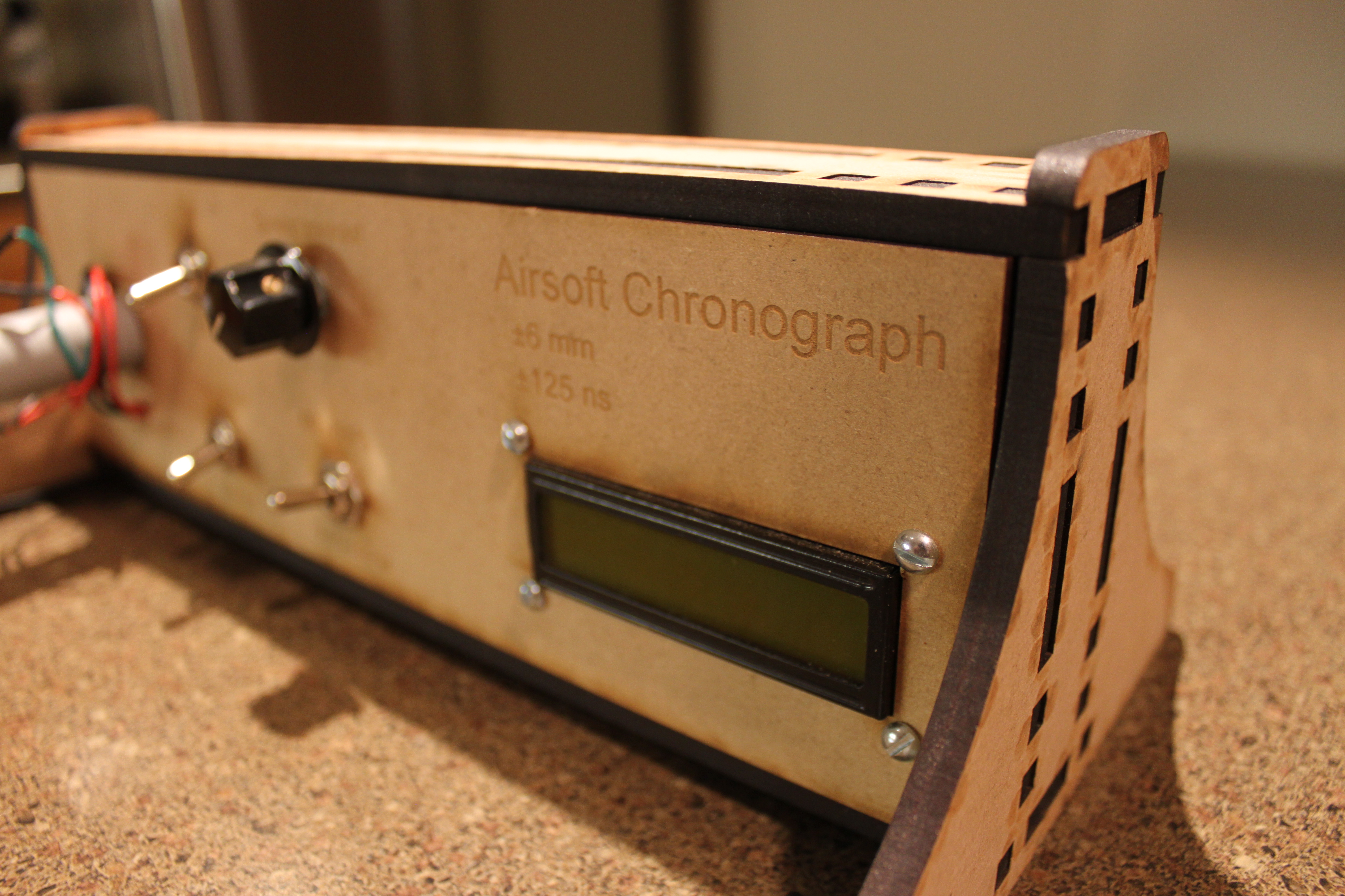
Airsoft photogate chronograph
Sometimes, you need a tool that performs as well as possible. This is not that. Sometimes, you need a tool that is cheap. This is not that. I did not, truly, need this tool, but there is something to be said for trying to build something just to see if you can. This is that.
An airsoft chronograph is a tool for determining the muzzle velocity (and, more importantly, muzzle energy) of an airsoft gun, or any other projectile device. These are a necessity for anyone who modifies or experiments with airsoft guns with hopes to actually use them in a game, since most airsoft fields restrict muzzle velocity to a certain number (typically, between 375 and 425 feet per second). A store-bought chronograph typically costs north of a hundred dollars. For what I believed could be accomplished with a pair of photogates and a microcontroller, this seemed too expensive.
So, of course, I set about building one from scratch.

For a start, I investigated various means of constructing a photogate.
A photogate consists of an emitter and a detector. The emitter is left on, and pointed at the detector. When the path between the two is obstructed, the electrical characteristics of the detector change. In an acceptable configuration, these changes are immediate, consistently timed, and need to be triggered in under the amount of time that it takes for the projectile to pass through the beam of light. With an airsoft pellet passing by a 5mm LED at somewhere shy of 500 fps, this is a tight timing window; the pellet obstructs the beam for about 40 microseconds, depending on how much obstruction it takes to trigger the sensor.
The options that became apparent were photocells and photodiodes. Through the magic of Ebay, a handful of photocells and photodiodes were acquired. The photodiodes were Siemens SFH309-FA5s. The photocells were generic cadmium photocells of no specifications. Also purchased were a few (100) infrared LEDs. Bench tests found that photocells were entirely ineffective for anything moving quicker than a waggling finger. Photodiodes, however, had no such trouble, given a well-tuned current-to-voltage detector (voltage divider where one leg is the sensor). Combined with a strong LED, these diodes could reliable trigger a pin-change interrupt on an ATMega
With my parts in hand, I drew a circuit diagram (not included here for having been thrown out a while ago) and soldered it together for a minimal prototype. There was duct tape and zip ties involved.
Photos of this stage of the project are not available, since the photos were lost in the churn of my phone dying a slow and painful death. That was an adventure for another day.
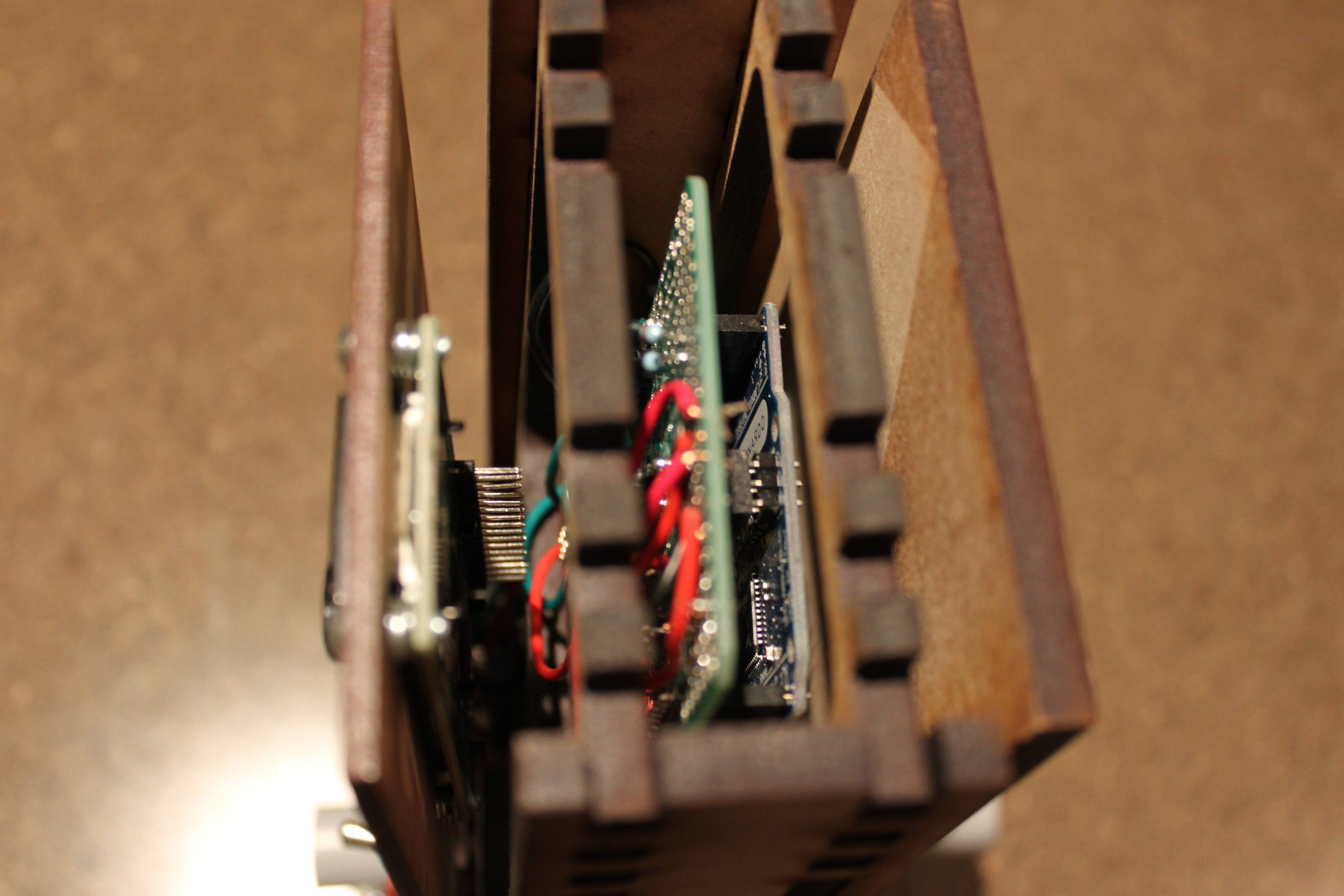
Once it had been found to work, a design consisting of more than duct tape and some scrap pine was needed. The electronics were soldered together on a permanent Arduino shield, and a contrast adjustment, power, units, and mode switch were added.
With all parts soldered together and screen attached, measurements were taken for an enclosure. The finger-joint box was designed in AutoCad, and the Centrepointe Imagine Space laser cutter was used to create the sheets from 6 and 3 mm MDF.


The finger joints fit together perfectly. Using lots of small tabs tends to let the kerf losses even out between parts. The photos above are the ssembly without any glue - removing the end cap took serious effort! The actual design of the box left a little to be desired, as I forgot to include a hole for the power cable, and the LCD had a few millimetres less clearance around its face than I had realized, leading to an oversized load.
The software running on the microncontroller was fairly simple, and can be found on GitHub. It works by attaching a falling-edge external interrupt to the pins associated with each photogate, and measuring the time between these two gates being triggered. The system loops over updating the screen, which provides information on the operation of the device and a readout of the data recorded.
The previously mentioned mode switch was configured to toggle between measuring muzzle velocity and measuring fire rate. Since this was a software change, no significant reworking was needed. The new software mode updates a clock and increments a counter when the front photogate is triggered. A shortcoming of this mode is that there is no way to reset the counter, other than by resetting the microcontroller with a quick tap of the power switch. Luckily, the device boots in milliseconds.
A few weeks after getting the whole unit together, I managed to get to a place with a real chronograph (And had a wonderful time while I was there). The Lucid L36 in question was clocked at around 365 feet per second. On my homebrew unit, it was clocked at around 359 feet per second. This is within the margin of error after accounting for battery charge levels, atmospheric pressure, temperature, cosine error through the chamber, and other potential issues.
By my measures, a resounding success.
There are a few shortcomings with this design. The tube that houses the photogates does not fit even the smallest muzzle break. So getting the shot to reliably pass through both photogate is a task that necessitates safety glasses and a willingness to hold the two tubes concentric by hand. This could be resolved with a redesign of the photogate to be wider than half an inch.
In summary, I'd say that it was worth trying to build one from scratch. Saved about 50% of the cost, and received entirely reasonable accuracy.